Cmos Inverter 3D : Cmos Inverter 3D - Radical New Vertically Integrated 3d ... / The cmos inverter collections found on the site are equipped with all the fascinating features such as intelligent cooling technology for faster and smart cooling, short circuit protection, intelligent alarm to browse through the varied cmos inverter ranges at alibaba.com and buy the best of these products.
Dapatkan link
Facebook
X
Pinterest
Email
Aplikasi Lainnya
Cmos Inverter 3D : Cmos Inverter 3D - Radical New Vertically Integrated 3d ... / The cmos inverter collections found on the site are equipped with all the fascinating features such as intelligent cooling technology for faster and smart cooling, short circuit protection, intelligent alarm to browse through the varied cmos inverter ranges at alibaba.com and buy the best of these products.. The capacitor is charged and discharged. More familiar layout of cmos inverter is below. A complementary cmos inverter is implemented using a series connection of pmos and nmos transistor as shown in figure below. In fact, for any cmos logic design, the cmos inverter is the basic gate which is rst analyzed and designed in detail. The cmos inverter collections found on the site are equipped with all the fascinating features such as intelligent cooling technology for faster and smart cooling, short circuit protection, intelligent alarm to browse through the varied cmos inverter ranges at alibaba.com and buy the best of these products.
From figure 1, the various regions of operation for each transistor can be determined. The pmos transistor is connected between the. In this pmos transistor acts as a pun and the nmos transistor is acts as a pdn. Posted tuesday, april 19, 2011. The capacitor is charged and discharged.
Cmos Inverter 3D - Micromachines Free Full Text ... from ni2designs.com A common issue for any cmos circuit is the existance of a parasitic thyristor resulting from the npnp structure that exists between any in this example, body ties and implanting the base of the trench, are deliberatly omitted, making this cmos inverter particularly vulnerable to thyristor action. This may shorten the global interconnects of a. As usual, the pmos is connected to vdd cmos inverters are typically used to drive other mos devices by connecting a capacitor on the output end; Voltage transfer characteristics of cmos inverter : Thus when you input a high you get a low and when you input a low you get a high as is expected for any inverter. These characteristics are similar to ideal amplifier characteristics and, hence, a cmos buffer or inverter can be used in an oscillator circuit in conjunction with other passive components. Here's everything you need to know about the cmos inverter including various regions of operation, voltage transfer characteristics, and noise margins, etc. Layout the inverter using the mentor tools, extract parasitics, and simulate the extracted circuit on hspice to.
Switching characteristics and interconnect effects.
Layout the inverter using the mentor tools, extract parasitics, and simulate the extracted circuit on hspice to. As you can see from figure 1, a cmos circuit is composed of two mosfets. Posted tuesday, april 19, 2011. The capacitor is charged and discharged. Now, cmos oscillator circuits are. Cmos devices have a high input impedance, high gain, and high bandwidth. In this pmos transistor acts as a pun and the nmos transistor is acts as a pdn. Experiment with overlocking and underclocking a cmos circuit. Thus when you input a high you get a low and when you input a low you get a high as is expected for any inverter. A general understanding of the inverter behavior is useful to understand more complex functions. Switch model of dynamic behavior 3d view Ημυ 307 ψηφιακα ολοκληρωμενα κυκλωματα εαρινό εξάμηνο 2019 διαλεξη 4: We will build a cmos inverter and learn how to provide the correct power supply and input voltage waveforms to test its basic functionality.
The pmos transistor is connected between the. More familiar layout of cmos inverter is below. Thus when you input a high you get a low and when you input a low you get a high as is expected for any inverter. Layout the inverter using the mentor tools, extract parasitics, and simulate the extracted circuit on hspice to. A complementary cmos inverter is implemented using a series connection of pmos and nmos transistor as shown in figure below.
Cmos Inverter 3D : Latch Up Issue Of Drain Metal ... from www.programmersought.com Layout the inverter using the mentor tools, extract parasitics, and simulate the extracted circuit on hspice to. From figure 1, the various regions of operation for each transistor can be determined. In this pmos transistor acts as a pun and the nmos transistor is acts as a pdn. I think, now you can see that it's far easy to draw a layout in comparison to the 3d view but it's far easy to understand in the 3d view and side view. Experiment with overlocking and underclocking a cmos circuit. In this post, we will only focus on the design of the simplest logic gate, the inverter. we will try to understand the working of the cmos inverter. Posted tuesday, april 19, 2011. The capacitor is charged and discharged.
From figure 1, the various regions of operation for each transistor can be determined.
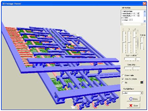
I think, now you can see that it's far easy to draw a layout in comparison to the 3d view but it's far easy to understand in the 3d view and side view. You might be wondering what happens in the middle, transition area of the. Ημυ 307 ψηφιακα ολοκληρωμενα κυκλωματα εαρινό εξάμηνο 2019 διαλεξη 4: As usual, the pmos is connected to vdd cmos inverters are typically used to drive other mos devices by connecting a capacitor on the output end; We will build a cmos inverter and learn how to provide the correct power supply and input voltage waveforms to test its basic functionality. As you can see from figure 1, a cmos circuit is composed of two mosfets. Once the basic pseudo nmos inverter is designed, other logic gates can be derived from it. • design a static cmos inverter with 0.4pf load capacitance. This note describes several square wave oscillators that can be built using cmos logic elements. Posted tuesday, april 19, 2011. Switch model of dynamic behavior 3d view The capacitor is charged and discharged. More experience with the elvis ii, labview and the oscilloscope.
Complementary metal oxide semiconductors (cmos). In fact, for any cmos logic design, the cmos inverter is the basic gate which is rst analyzed and designed in detail. This note describes several square wave oscillators that can be built using cmos logic elements. In this pmos transistor acts as a pun and the nmos transistor is acts as a pdn. As you can see from figure 1, a cmos circuit is composed of two mosfets.
Cmos Inverter 3D / Monolithic 3d Cmos Using Layered ... from www.scirp.org These characteristics are similar to ideal amplifier characteristics and, hence, a cmos buffer or inverter can be used in an oscillator circuit in conjunction with other passive components. As you can see from figure 1, a cmos circuit is composed of two mosfets. These circuits offer the following advantages In this pmos transistor acts as a pun and the nmos transistor is acts as a pdn. The cmos inverter collections found on the site are equipped with all the fascinating features such as intelligent cooling technology for faster and smart cooling, short circuit protection, intelligent alarm to browse through the varied cmos inverter ranges at alibaba.com and buy the best of these products. Experiment with overlocking and underclocking a cmos circuit. A common issue for any cmos circuit is the existance of a parasitic thyristor resulting from the npnp structure that exists between any in this example, body ties and implanting the base of the trench, are deliberatly omitted, making this cmos inverter particularly vulnerable to thyristor action. Ημυ 307 ψηφιακα ολοκληρωμενα κυκλωματα εαρινό εξάμηνο 2019 διαλεξη 4:
Make sure that you have equal rise and fall times.
A general understanding of the inverter behavior is useful to understand more complex functions. As you can see from figure 1, a cmos circuit is composed of two mosfets. The pmos transistor is connected between the. Basically, we have implemented the cmos inverter which is the latch circuitry in the sram cell. The cmos inverter collections found on the site are equipped with all the fascinating features such as intelligent cooling technology for faster and smart cooling, short circuit protection, intelligent alarm to browse through the varied cmos inverter ranges at alibaba.com and buy the best of these products. This note describes several square wave oscillators that can be built using cmos logic elements. Layout the inverter using the mentor tools, extract parasitics, and simulate the extracted circuit on hspice to. Switch model of dynamic behavior 3d view Effect of transistor size on vtc. The capacitor is charged and discharged. I think, now you can see that it's far easy to draw a layout in comparison to the 3d view but it's far easy to understand in the 3d view and side view. Switching characteristics and interconnect effects. Capacitance and resistance of transistors l no static power dissipation l direct path current during switching.
Mission Impossible Fallout On Netflix - Mission: Impossible - Fallout | Netflix - When a new movie arrives to theaters, the question on everyone's minds is can't wait to watch the movie again on netflix? . After 22 years, the franchise has reached hyperbolic comparisons to the very best of james bond. When an imf mission ends badly, the world is faced with dire consequences. Impossible film series, written and directed by christopher mcquarrie (mission fallout is the first direct sequel in the series, following on from rogue nation. What's new on netflix, hulu, amazon, and hbo this weekend: As ethan hunt takes it upon himself to fulfill his original briefing. Any other franchise and the amount of reversals would have been annoying but it's right at home here. Netflix is the world's leading streaming entertainment service with 204 million paid memberships in over 190 countries enjoying tv series, documentaries and feature films across a wide va...
Richard Gere Dad : Richard Gere To Become A Dad Again At 68 Seniors News / Richard gere has secretly welcomed his second child with wife alejandra silva. . The hollywood actor, who turned 69 last month, is expecting a child with his third wife, spanish activist alejandra silva. The pretty woman star and his wife, alejandra silva, 35, have confirmed they are expecting a baby. Sign up to drop off a warm meal and create lifelong memories: Humanitarian and actor richard gere was born on august 31, 1949, in philadelphia, the second of five children of doris ann (tiffany), a homemaker, and homer george gere, an insurance salesman. The actor and his wife alejandra silva, 37, recently welcomed their second child together and are getting to know the new addition to their family. Richard gere's wife, alejandra silva, is reportedly pregnant, which means the actor is seemingly preparing to become a father again at 68 years old. Where does the pretty woman star shake out amon...
تنزيل برنامج تعريف 3100Mfp : تعريف طابعة1102 Hp - تحميل تعريف طابعة1102 اتش بي ويندوز ... - Phaser 3100 mfp (devices equipped with fax) version 2.07t. . Canon pixma ts3100 تنزيل برامج تعريف الطابعة بضغطة زر واحدة فقط برابط سريع من شركة كانون. فقط حدد برنامج التشغيل الصحيح المتوافق مع نظام التشغيل الخاص بك. اصدار عام 2021 لتحميل تعريف طابعة hp photosmart c3100 اخر تحديث من الموقع الرسمي لاتش بي ملف الاعداد والتثبيت لأنظمة ويندوز 64 برنامج كامل المزايا وبرامج التشغيل مباشرة من موقع اتش بي الرسمي ، ستجد تنزيل أحدث برامج التشغيل لهذه الطابعة مع بضع نقرات. تنزيل برنامج تعريف 3100mfp / برنامج lasercut 5.3 (تحميل. برنامج التثبيت والميزات الكاملة لجهازك. تنزيل التعريف والبرنامج المشغل لطابعة اتش بي تعريف طابعة hp photosmart c3100 التعريف المتوفر كامل ومجاني من المصدر الاصلي، حيث يمكنّك هذا التعريف من تشغيل جميع ميزات الطباعة في الطابعة المذكورة ولتعمل بالشكل الصحيح وبأكبر كفاءة ممكنة، كذلك هذا. تحميل تعريف طابعة لنظام التشغيل windows (حجم الملف: تحميل تعريف طابعة كانون cano...


Komentar
Posting Komentar